CU Rigging Notes
v.12/2019
Maintenance information is in the Equipment officer’s guide.
Warning: this is not a full rigging guide, do not rig CU if you have not been shown how to by somebody who knows how to rig CU. This guide is just to remind a trained person of some key points.
The ultimate reference is the current version of the flight manual which takes precedence over anything written in this guide. This guide is not meant to be a substitute for the flight manual. The flight manual is kept in the CU folder in one of the cupboards in the workshop.
Rigging CU is quite easy and two people who know what they are doing can rig in 20 minutes. However, ASW19s are at heightened risk of rigging related accidents due to disconnected controls, so make sure you have rigged correctly.
Contents
Pre-rigging notes
Some basic rules and things to be aware of:
- Never rig the glider unless you are 100% sure you know what you are doing, If you are unsure get help from an Instructor or somebody who is familiar with an ASW19;
- Don’t get distracted or interrupted during the rigging process, this is how you forget something;
- Alway do a full DI and positive control checks before taking the glider to the launch point;
- Always get a full briefing and read the flight manual before a conversion flight;
- 60% of accidents caused by disconnected elevators happen on ASW19 or 20s, double check the elevator connections before flying.
Rigging
You need at least 2 people to rig CU, but 3 is helpful.
- Unlock trailer at both ends and open
- Remove trestles, ramp, ramp handles, etc
- Lower the end of the trailer if needed. Extend the trailer legs to stop it from wobbling.
- Remove carpet from wing tips and cover trailer corners
- Attach the ramp to the end of the trailer, the pivot jack at the end should be in the low position with the wheel extended AWAY from the trailer side.
- Move wings out to edge of trailer
- Undo blue strap that holds the tail down (may not be attached when the trailer is parked)
- Lift fuselage by black handle around tail and slide out of trailer (mind the top of the fin as you come out)
- Remove strap though fuselage, and tennis balls. (Tennis balls may not be installed when the trailer is parked)
- Remove strap on the tail
Connecting the starboard wing (right)
Always rig the wing with the fork first.
- Person 1 lifts wing tip and slides wing out of trailer (mind the pins on the fuselage and the edge of the trailer)
- Once fully out, person 2 lifts root and carries out wing
- Rotate wing and place spar in hole in fuselage (make sure that the fuselage doesn’t wobble)
- Slide wing in (make sure that the control rods don’t catch on the fuselage)
- Once fully in, person 2 places trestle under the tip, person 1 can relax.
Connecting the port wing (left)
Repeat as for the starboard wing.
Inserting the main pins
Inserting the pins should be a quick an easy task taking less than a minute, if they are not going in the wings are not level and not aligned correctly.
- Person 1 removes a pin from green bag (they are identical). The orange bag is stored under the seat cushion when the glider is de-rigged.
- Person 2 lifts one wing tip.
- Person 1 inspects the pin holes, behind the seat in the spar, and gives instructions to person 2 to move the wing tip up/down so that the holes in each spar align. Check that the wings are flush with the fuselage, if not it may be necessary to move the wing tip forward/backward to achieve alignment.
- Person 1 inserts pin into one of the holes as far as it will go (usually about half way).
- Person 1 removes the second pin and inserts it in the second hole fully. This may require some additional moving of the wing tip by person 2.
- Person 1 then can push pin 1 fully in.
- Rotate the pins so that handles meet, lock them in place with the safety catch halfway between the pins.
- Person 2 can now relax.
Connecting the tail plane
- Person 1 & 2 stand in the trailer at each end of the tailplane, which is attached to the roof of the trailer.
- Person 2 (at the back of the trailer facing forwards) supports the tailplane
- Person 1 (at the front facing backwards) pushed the handle on the back support to his left, the support will drop and person 1 catches it so that it does not crash into anything
- Remove the tailplane and avoid scratching the glider with it
- Lower the tailplane onto the fin and then push backwards to lock in place
- Use the metal wire to pull back the small metal loop on the top of the tail plane, place the bolt into the tailplane a do up with the allen key. Note that the metal loop is very fragile. If it gets damaged it will need cutting out of the tailplane, which is very expensive.
- Tighten the bolt as far as it will go and then loosen one notch, the metal loop will fit into one of the cuts in the bolt.
Lower the main wheel
- Lift the fuselage up using the jack if required
- Lower the main wheel using the lever in the cockpit
- Lower the jack using the bar stored on the left inside side of the trailer
- Gently push the glider back on the belly dolly
Connect the controls
This is a safety critical action and must be done correctly; check and double check control connections.
- Remove wing guards from each wing, careful not to bash the point where the aileron connectors are.
- Remove the protector from the elevator control.
- Connect each control by:
- Pulling down the collar
- Pushing the pin sideways through the rod
- Putting the socket over the ball
- Allowing pin to spring back
- Allowing collar to spring back
- Checking that pin cannot move fully when the collar is up
- The controls that need connecting are
- 1 x elevator (trim back before connecting)
- 2 x airbrakes (unlock air brakes by pulling the rods in)
- 2 x ailerons
- Ailerons and air brake controls can be accessed from the little panel behind the cockpit.
- Once controls are connected, close and lock the little panel. Make sure that the little panel is taped up securely with a wing tape, as the locking mechanism does not lock it fully.
Install total energy tube
- Total energy tube is kept in the pocket in the cockpit
- Slide into the hole in the fuselage halfway between the wings and the tail
- Don’t push too far, the lip on the total energy tube should be flush with the glider, don’t push it any further or you will damage the glider
- If it is pushed too far the tube would be blocked and there will not be any reading of the vario
- The two small holes on the tube should face backwards
Install batteries
- Batteries are stored in the back of the hangar and are marked CU
- Batteries go into the holders behind the pilot's head and are held by straps
- Plug battery wire into connectors
Install Vertica (optional)
Status of the vertica is UNKNOWN, you are advised to use XCSoar on your phone.
- Vertia flight computer is kept in the CUGC box below the parachute room
- Plug in the usb power cable
- Place into holder (bottom first) and it will click into place
Install glide computer (optional)
- Mount the glide computer using the RAM x-grip mount in the centre of the instrument panel
- Adjust the positioning by slightly loosen the two screw handles, make sure NO INSTRUMENT IS COVERED BY THE PHONE, then tighten the two screws again
- Plug in the usb power cable. You may need an adaptor, since the cable has an old micro USB connector
Wing tape
You should always tape up:
- The control connections access panel
- Base of the total energy tube
For improved performance you can also tape up:
- Gap between the wing and the fuselage x2
- Gap between the fin and the tailplane
- Over the tail plane bolt (avoid the little metal loop)
Ballast weights (as needed)
Ballast weights are stored in the CUGC shelf in the parachute room.
- Check ballast requirements and remember the conversion between ballast weight and equivalent pilot weight (x2.5)
- Ballast weight go in the nose
- Remove the nut (don’t lose)
- To add a ballast weight you will need to slightly close the canopy
- Replace the nut and secure the ballast weights
Daily inspection
ALWAYS PERFORM A DAILY INSPECTION AND POSITIVE CONTROL CHECK BEFORE FLYING THE GLIDER
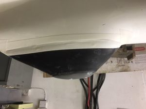
During daily inspections make sure that you check the condition of the glider’s skid. If the bottom foot is worn, the glider is U/S and skid needs replacing. Please see a picture of new skid for reference.
Soartronics BT connector
This is a device placed between the flarm and flarm display. It is essentially an serial connection to the flarm over the bluetooth. Once the flarm is powered on the device should be discoverable by bluetooth and should be paired to the mobile phone (PIN 1234 if prompted). With appropriate settings with the XCSoar, the following functions are supported:
- Flarm radar (display of the local traffic)
- Adjust flarm setting
- Declare task to the flarm IGC recorder before taking off
- GPS and barometric height (if your phone does not built-in GPS/barometer)
For more information please see:


